go to Tutorials Page | go
to 3DKingdoms.com
by Jonathan Kreuzer (All 3D models by Josh Hess)
www.3dkingdoms.com
( DEC 2nd, 2002 ) This tutorial has been updated with more info in many places,
and may be updated or changed periodically.
( MAY 15th, 2005 ) I updated this tutorial page. Changes to its contents are
mostly minor. Not all changes are marked, but some are marked with "update"
( MARCH 26th, 2006 )
I made more changes to simplify/streamline this tutorial and bring it up to date, including updating some code. There's still dated info mixed in, and I haven't updated the images. I dropped the quaternions from this page.
I use quats to store joint rotations, but I use matrices in the calculations presented here. Hopefully this tutorial is better now and not worse =)
code is given in C++, using OpenGL for rendering.
Contents - Normal Mapping Tutorial
Related Links:
From my Weekly Articles: Skeletal Animation #1 | Normal Mapping Shader | Quaternions | Matrices | 3d Vectors | Tangent Space
Graphics programming with OpenGL: www.opengl.org
3D graphics papers, programs, and programming info for NVidia cards: developer.nvidia.com
3D graphics papers, programs, and programming info for ATI cards:
www.ati.com/developer
Normal Mapping Tutorial Introduction:
This tutorial will tell you about object space normal mapping of skeletal animated meshes in OpenGL. This is a technique I use in my 3D animator and editor program (3D Kingdoms Creator.) I'm sure plenty of other people have used this technique, but since I haven't seen any tutorials on it, I thought I'd write one myself. The general type of normal mapping described here is now being used in games though I've seen it discussed around 5 years before I wrote this tutorial in 2002. It is a slight possibility I'll add some kind of working demo sample, but to rip and reassemble relevant portions from a megabyte of code is not something I particularly want to do.
Please Note: This tutorial leaves out some optimizations that I've done, but the code and technique given should still run at a decently fast framerate. Also the decisions about what was the easiest way to do something were made with a specific program (now named 3D Kingdoms Creator) in mind, so if you handle the rendering of your skeletally animated models differently than I do, the best way for you to do the calculations involved in object space normal mapping may differ as well. Even now I do some skeletal animation a bit different from when I originally wrote this code, I've made some updates, but I'm not sure if everything matches up anymore. The code snippets given were taken from a working program, but they were changed for the tutorial, so I wouldn't be surprised if I introduced some bugs.
This tutorial assumes familiarity with OpenGL and skeletal animation. There are some links at the top of the page to brush up on these subjects.
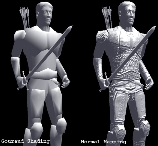
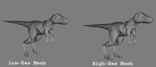
Normal-Mapping is a technique used to light a 3D model with a low polygon count as if it were a more detailed model. It does not actually add any detail to the geometry, so the edges of the model will still look the same, however the interior will look a lot like the high-res model used to generate the normal map. The RGB values of each texel in the the normal map represent the x,y,z components of the normalized mesh normal at that texel. Instead of using interpolated vertex normals to compute the lighting, the normals from the normal map texture are used. The low resolution raptor model used for this tutorial has 1100 faces, while the high res model has 20000 faces. Since the high-res model is used only to generate a texture (which I'll refer to as the normal map,) the number of polygons in the high res model is virtually unlimited. However the amount of detail from the high-res model that will be captured by the normal map is limited by the texture's resolution. Below is a screenshot of a warrior with plain gouraud shading, and one with normal-mapped shading and specular lighting (he's uniformly shiny because the specular intensity map is in the diffuse texture alpha channel, so not used in this shot.) Also below are the meshes used to generate the raptor normal map in this tutorial.
Object Space and Tangent Space:
Whether using object space or tangent space, normal-mapping with skeletal animation is much the same. The main idea behind using tangent space is going through extra steps to allow the reuse of a normal map texture across multiple parts of the model (storing normals/tangents/binormals at the vertices, and computing the normals of the normal map relative to them, then converting back when rendering. Also, you could use tangent-space to skin a flat bump texture around a model.) See the Tangent Space article for a more detailed description of computing and using these vectors. By writing a tutorial on object space, I'm not saying object space is better. However it does have some advantages, and is certainly a usable approach. I only use object space for normal maps generated from a high-res mesh, but I use tangent space for bump-mapping on levels. Below are a few of my personal thoughts on the two methods for those interested, but be aware that there are some tricks or different ways to do things with any method.
Advantages to using Object Space :
It's simpler to implement and I find it more straightforward to think about. The normal map contains the normals pointing in their actual directions (for an unrotated model at least.) You get to forget about per vertex normals, tangents, and binormals ( which I'll call n/t/b for short. ) This means less initial calculations, and you don't have to worry about poorly behaved n/t/b causing distortion. It's also slightly faster because you don't have to rotate the n/t/b with your model, or convert light vectors to tangent space. Level of detail algorithms or anything else that reduces and changes the vertices in your model can easily run fine. (In tangent space the changing n/t/b interpolations caused by removed vertices would probably distort the mesh normals, although I'm not sure if it will be noticeable. ) Object space may have less noticeable seems at texture uv boundaries than tangent space, but this depends greatly on the meshes and implementation.
Disadvantages (as opposed to Tangent Space) :
You can't reuse texture coordinates for symmetric parts of the model. If you
had a model that is completely symmetric along an axis, and 1 MB normal map,
that means 0.5 MBs of it is redundant information. If this bothers you, keep
in mind this is only for something rendered as one piece. In the case mentioned
above you could render the model in two halves, each using the same normal map,
but one rendered with the light vector x component reversed ( or y or z depending
on the axis of symmetry. ) Which is a tiny bit of extra work, but this is what
I do myself. (My skeletal meshes have always had a chunk system, and flags settable
per chunk, so flip x,y,z can be set to re-use parts of the texture.)
Another main disadvantage to not using tangent space is that you can't use a
detail normal map for fine close-up detail in addition to the one that approximates
the high resolution mesh. (You can add details into the object space normal
map when generating it, however, a detail normal map would be highly repeating,
thus offering much greater resolution than just using the one normal map.)
Also Tangent Space normal maps can be more easily compressed by storing only the X,Y channels. Since the normals
are unit vectors, and the Z channel is always in the same direction, the Z channel can be computed this way: Normal.z = sqrt( 1.0 - Normal.x*Normal.x - Normal.y*Normal.y );
A small issue to be aware of is that using mipmaping with normal
maps can sometimes cause visible seems when downsampling causes the uv coordinates to
align improperly with the texture. To fix this you can extend the edges on the
normal map texture, or use fewer or no mipmaps. In tangent space mis-aligned
UVs don't matter as much, since the texture is mostly blue (z-component).
A limitation of Object Space normal mapping, as opposed to using Tangent Space, is that every point on the skin must have its own distinct UV coordinates. You can't reuse parts of the texture for multiple parts of the model. This is a pretty common practice: perhaps both sides of the Raptor's face will have the exact same UV coordinates, effectively reusing one part of the texture for both sides of the face. With the straightforware implementation of an object space normal map though, the normals on opposite sides of the Raptor's face will obviously have to point in different directions, so they each need to be defined by separate areas of the texture. There is a way around this for parts of a model that are completely symetric along an axis. Only generate the normal map for one side, and then render each side separately, and when rendering the mirrored part of the model, instead of mirroring the texture normals, mirror the light vector.
Once you have a high-res and low-res model, you'll need something to generate
the normal map. I suggest, rather than spending the time to write a program
to do it yourself, go to www.ati.com/developer/tools.html
and click on "Normal Mapper" to download the program. What the ATI
normal mapper does is cast a ray from each texel on the low-res model, find
the ray's intersection with the high-res model, and save in a texture map the
normal from the high-res model where the ray intersects. The program includes
source, so it could be a good example if you want to write your own program
to generate normal maps. You'll need to export the models to .nmf format using
the exporters provided, or write a converter yourself. Here's a sample command
line to generate a 512x512 pixel normal map:
"normalmapper w raplow.nmf raphigh.nmf 512 512 rapnorm3.tga"
The 'w' is needed to tell the normal mapper to leave the normals in world space
instead of converting to tangent space. However the program offers many other
options, and you should definitely read the readme.txt file that comes with
it and play around to try to figure out how to get the best normal map.
Update: NVidia now has a normal map generator named Melody on their developer's page. Some differences from the ATI normal mapper are that Melody has a graphical user interface, and it doesn't come with source code. I don't have much experience using it since it's not what I use currently, so I can't give any hints for using it, but I'd guess that some people would find a GUI with a preview window to see how the normal map looks easier to use.
I wouldn't be surprised if you needed to fix certain things about the normal map by editing it in an image editing program. Like you may want to invert the red channel if the left side lights up when the light is on the right, or there may be some stray pixels or lines generated by the normal mapper that you want to get rid of, or just general editing that is easier to do to the normal map than the high-res model. It's often easier to see what's happening with editing or smoothing parts of the normal map if you do it one channel at a time instead of at full RGB. If you do any editing other than just inverting channels, you probably should re-normalize the image. (When I want to re-nomalize, I just call a function for each pixel I load that converts the RGB values to floats to the -1 to 1 range, calls Normalize (R, G, B), then converts back to unsigned chars.)
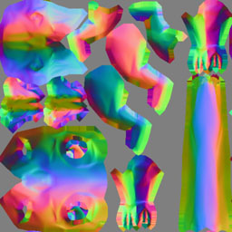
(The normal map,
displayed at half size )
We want to use the normals from the normal map for per-pixel lighting. This type of setup is sometimes called Dot3 bumpmapping. All the OpenGL code on this page uses extensions, which you'll have to have defined to compile. You can download the file glext.h from the SGI Developer page. That page also has a list and descriptions of all the extensions. If you haven't used gl extensions before, you'll probably want to search the web for sample source that uses them to see how to define them.
The easiest way to see a normal map in action is to use this code, although different techniques are needed for advanced lighting models:
glTexEnvf (GL_TEXTURE_ENV, GL_TEXTURE_ENV_MODE, GL_COMBINE_EXT); glTexEnvf (GL_TEXTURE_ENV, GL_COMBINE_RGB_EXT, GL_DOT3_RGBA_EXT); glTexEnvf (GL_TEXTURE_ENV, GL_SOURCE0_RGB_EXT, GL_PRIMARY_COLOR_EXT); glTexEnvf (GL_TEXTURE_ENV, GL_OPERAND0_RGB_EXT, GL_SRC_COLOR); glTexEnvf (GL_TEXTURE_ENV, GL_SOURCE1_RGB_EXT, GL_TEXTURE); glTexEnvf (GL_TEXTURE_ENV, GL_OPERAND1_RGB_EXT, GL_SRC_COLOR); |
Register combiners ( old ): This is now a quite old tutorial, but the part on register combiners is probably the most dated info, so I recommend ignoring it. Of course, if you're targeting a GeForce 1-4, register combiners may offer better performance. If you want you can view the register combiners section here.
Cg (update): I use NVidia's Cg currently, which I like much better than register combiners, but it didn't exist when I first wrote this article. I've tried my Cg shaders on recent ATI cards, and they've worked with the ATI cards as well as the NVidia cards. (There are a few exceptions... not all Cg shaders will work on ATI cards too, although the problem is more related to the different features the cards support than Cg itself.) Once I had Cg for OpenGL set up in my program it was very easy to work with, but to get Cg to work with your programs you'll need to get the toolkit from Nvidia's page and do a fair share of reading. Also to run Cg programs you'll need the .dll files from the NVidia Cg page linked to above. Another possibility that I may try out sometime is the OpenGL Shading Language.
Here's the sample Cg Code for one colored light + ambient on a normal mapped model, with distance attenuation in the vertex shader. The light vector is calculated in software per vertex and just passed through. This is to be consistent with the sections left over from the original version of this tutorial. However, I find it's better to calculate it in the vertex shader. Cg shaders could easily have their own entire tutorial, so I'm just presenting a single simple one. I've put it together from parts of more complicated code, I hope it still works.
Vertex Shader:
void main( float4 Pobject : POSITION, float2 TexUV : TEXCOORD0, float3 inL : COLOR0, uniform float4x4 ModelViewProj, uniform float3 lightPosOS, // OS = in Object Space uniform float lQ, // Light intensity, for distance attenuation uniform half3 lightColor, out float4 HPosition : POSITION, out half4 L : COLOR0, out float2 uv : TEXCOORD0, out half3 LV : TEXCOORD1 ) { HPosition = mul(ModelViewProj, Pobject); uv = TexUV; LV.xyz = inL; float d = distance( lightPosOS, Pobject ); L.xyz = lightColor * saturate ( 1.0 / (lQ * d * d) ); } |
// // lColor = light color, uv = texture coordinates for normal map and diffuse map, // LV = light vector, the ambientColor constant is set with cgGLSetParameter3fv. // half4 main( half4 lColor : COLOR0, half2 uv : TEXCOORD0, half3 LV : TEXCOORD1, uniform sampler2D diffuseMap : TEXUNIT0, uniform sampler2D normalMap : TEXUNIT1, uniform half3 ambientColor) : COLOR { half3 N = tex2D( normalMap, uv ).xyz * 2.0 -1.0; half NdotL = saturate( dot(N, LV * 2.0 - 1.0) ); half3 C = saturate( lColor * NdotL + ambientColor ) * (half3)tex2D(diffuseMap, uv).xyz; return half4(C, 1); } |
Texture1 is the normal map texture and Texture0 is the diffuse texture (sometimes referred to as the 'skin texture'.) The R,G,B components of the normal map, which represent the x,y,z of the model normal at that texel, are dot-producted with the light vector which is sent in as the primary color component for each vertex. The light vector is linearly interpolated between vertices, (and the normals are interpolated between texels), which can cause small lighting artifacts (a darkening where it becomes unnormalized.) While the interpolated light vector can be renormalized per pixel, I've just left it as is, because this is plain, quick code. Also, depending on the diffuse texture (detail or graininess does a good job of hiding small lighting artifacts), and mesh and lighting used, the difference may not be noticeable. (More Info on this)
There's still one thing left to do though, and that's compute the normalized light vector. For a moving mesh or light, this will have to be recomputed every frame. However, I'll start by describing the computation for a mesh that hasn't been moved or rotated at all. The computation is done per vertex, so for each vertex in the non-moving model, the light vector is defined by lightVector = lightPosition - vertexPosition. Call Normalize (lightVector). You then scale the x,y,z components to the 0-1 range and store them a float array to be called later. You may want to do per vertex lighting attenuation on the stored light vector by simply scaling the x,y,z components by less than .5 based on the some function of the distance between lightPostion and vertexPosition. Most moving meshes will be well-tessellated, and the difference in lighting from one vertex to the next due to distance attenuation will be quite small, unlike lighting due to angle, which may change greatly between adjacent vertices. So it usually makes sense to do distance attenuation on a per-vertex basis instead of a per-pixel basis. Also note, I've already computed the world coordinates of all the vertices in the mesh and stored them in the array Mesh.RenderVertices. (Which is trivial here, since the model hasn't moved at all, but it's important to note that RenderVertices contains world-space coordinates for later.) Also be aware that you may have to swizzle(ie. swap around) which lightVecs x,y,z elements the lv.x, lv.y, and lv.z are put into to get it to match up properly with the normal map x,y,z if you use a different normal map format or coordinate system than I do. All the vertices and vectors are declared using my vector class.
for ( nVert=0; nVert < Mesh.numVertices; nVert++ )
{
   lv = lightPos - Mesh.Vertices[ nVert ];
   lv.Normalize();
   lightVecs[ nVert ] = lv * 0.5f + CVec3( 0.5f, 0.5f, 0.5f );
}
|
Now that you know how to generate the light vectors for a model that hasn't moved, let's try one that has. For example, suppose your entire model has been rotated. All the normals on your normal map are still exactly the same, so they're all wrong now, and we've got to correct for this. Instead of updating each texel of the normal map, we rotate the light into object space, and computer the light vectors using the object space light. In the following example the rotation of the model is defined by the Matrix M.
// The Matrix M stores the translation and rotation of the mesh InvM = M.Invert(); lightPosOS = InvM * lightPos; for ( nVert=0; nVert < Mesh.numVertices; nVert++ ) { lv = lightPosOS - Mesh.Vertices[ nVert ]; lv.Normalize(); lightVecs[ nVert ] = lv * 0.5f + CVec3( 0.5f, 0.5f, 0.5f ); } |
Light Vector Computing Per Vertex for Skeletons
Okay, but now what about the rotation of individual joints in your skeleton? I'm
assuming that each joint is the parent of a bone with vertices attached to it,
and thus I'll refer to vertices as attached to joints. A rotation for a joint effects all its children too.
Every frame, or whenever the skeleton moves, you'll recompute the matrices for each joint (pBoneMatrix).
You can call a recursive process joint function that starts at the parent joint, multiplies the child joints by the parent matrix and saves them.
The skeleton is bound to the mesh in a certain position where it will not deform the mesh at all.
I'll call this the rest position, I've also heard it called the bind pose.
In the rest position you'll save the inverse of the matrix for each joint into an array (pInvBindMatrix).
Look here for more details about computing joint matrices and skeletal animation.
This code uses my matrix class.
Here I'm using the world-space vertex locations, and just rotating the light vectors. You also could try computing a
joint-space light location for each joint and use that with the object-space mesh vertices.
CMatrix MInvBones[ MAX_BONES ]; for ( int nBone = 1; nBone < Skeleton.nTotalBones; nBone++) { // InvertRot sets the translation component of the matrix to the identity MInvBones[ nBone ] = (pInvBindMatrix[ nBone ] * pBoneMatrix[ nBone ]).InvertRot(); } for ( int nVert = 0; nVert < SkeletonMesh.numVertices; nVert++) { lv = lightPos - RenderVertices[ nVert ]; lv.Normalize(); nBone = Skeleton.BoneAttached[ nVert ]; if (nBone == 0) continue; // I have no bone 0, so this means no attachment outlv = MInvBones[ nBone ] * lv; lightVecs[ nVert ] = outlv * 0.5f + CVec3( 0.5f, 0.5f, 0.5f ); } |
Vertex Weighting with multiple attachments
Another thing to note is that for skeletal animation with vertices only attached to one joint, medium or large rotations will cause a noticable seam in the lighting where vertices connected to the rotated joint are adjacent to vertices connected to its parent joint. The solution is to attach each single vertex to multiple joints, with a weight for each attachment. You also may want to add more vertices to the model in problem areas. These weights are also used to compute the vertex (x,y,z) position so weighted attachments are fairly standard even for unlighted meshes. The unnatural vertex bunching at joints often caused by vertices only attached to one bone is itself a large cause of lighting seams.
The weights for a vertex should add up to 1. For example, a vertex may be attached to 2 joints, one with a weight of 0.4 the other 0.6. If you were using standard lighting, the vertex normal would be the weighted average of each normal calculated for each joint the vertex is attached to. In this example: VertexNormal = normal1 * weight1 + normal2 * weight2. You handle lighting with weighted vertices in object space normal mapping exactly the same way, only you average the light vector instead of the normal. VertexLightVector = LightVector1 * weight1 + LightVector2 * weight2. Remember to normalize VertexLightVector. For skeletal animation in general with low poly models there may still be lighting problems(and vertex position problems) at joints for large rotations even with weighted vertices. There's an art to doing the attachments and having enough & well-placed vertices in the low poly model.
Now all that's left is rendering your model. Assuming you've done all the setup necessary for the normal-mapping, and the placement of your model, here's the OpenGL code to draw it:
ComputeLightVectors(); // calls a function to update the lightVecs array, such as the one given above InitRegisterCombiners(); // calls a function of yours to setup the register combiners such as the one given in this tutorial. glEnableClientState( GL_COLOR_ARRAY ); glColorPointer( 3, GL_FLOAT, 0, lightVecs ); glEnableClientState( GL_VERTEX_ARRAY ); glVertexPointer( 3, GL_FLOAT, 3 * sizeof(GL_FLOAT), Mesh.RenderVertices ); // diffuse map texture with texture unit 0 glActiveTextureARB(GL_TEXTURE0_ARB); glClientActiveTextureARB(GL_TEXTURE0_ARB); glEnableClientState(GL_TEXTURE_COORD_ARRAY); glTexCoordPointer(2, GL_FLOAT, 2 * sizeof(GL_FLOAT), Mesh.UV ); glEnable(GL_TEXTURE_2D); glBindTexture(GL_TEXTURE_2D, DiffuseTexture); // normal map texture with texture unit 1 glActiveTextureARB(GL_TEXTURE1_ARB); glClientActiveTextureARB(GL_TEXTURE1_ARB); glTexCoordPointer(2, GL_FLOAT, 2 * sizeof(GL_FLOAT), Mesh.UV ); glEnableClientState(GL_TEXTURE_COORD_ARRAY); glBindTexture(GL_TEXTURE_2D, NormalMapTexture); glEnable(GL_TEXTURE_2D); glDrawElements( GL_TRIANGLES, Mesh1.numfaces*3, GL_UNSIGNED_SHORT, Mesh.faces); |
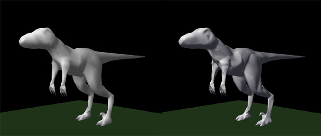
Below is a comparison of the normal mapped low-res model to low-res model lit by standard lighting. Also note that for a moving light, in gouraud shading where lighting and normals are per vertex the lack of precision and polygon boundaries are easily noticeable, yet normal mapping avoids these problems. The high res model used for the normal map was in this case generated by just tessellating the low res model. It would look even better if more shaping was done and more details were created. In addition, the ATI normal mapper contains an option to perturb the normals by a bump map before placing them in the normal map, which could further increase the small detail in the normal map, so usually I use this option.
|
(Gouraud shaded low-res model on left, normal mapped low-res model on right, both with a flat gray diffuse texture to show the lighting better)
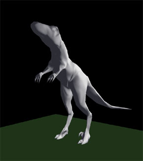
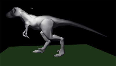
(These last 2 screenshots show the normal mapped low res model with mesh deformation.) |
( At the 3D Kingdoms Creator page you'll find some screenshots with normal mapped models. )
Appendix (Per Pixel Normalization):
With the dot product, the magnitude of the vectors (normal & light vector) control the magnitude of the scalar output (brightness). If one of these is shorter than the unit vector, then it will result in smaller output, and thus darker lighting. The darker spots are because linearly averaging two unit vectors, as is done with the light vector between vertices, or the normal map between texels, results in a vector of reduced magnitude. The greater the angle between the two vectors, the smaller the magnitude of the averaged vector, with 180 degree vectors cancelling out completely. The curve followed by normalized interpolation between unit vectors (labelled V1 and V2), and the line followed by linear interpolation are illustrated below.
Now there is a question as to how noticeable this is in your program. If it's not very noticable then you can ignore per-pixel normalization. (How noticable depends on a lot of factors. A more tessellated model, or a higher resolution normal map, means less interpolation. More detailed/grainy diffuse textures hide lighting artifacts. Strong specular highlights make the unnormalization much more noticable. It also depends on how closely the model will likely be viewed, etc.)
Interpolating vectors between vertices is handled by the graphics card, but
the vectors can still be renormalized at the cost of extra operation(s).
Now, the newer graphics cards provide a normalization function on the GPU
that is reasonably fast, though it still will result in a slower fill rate. Whether it's almost free or noticeably slower depends on the graphics card.
For
a Cg shader, you can just use something like lightV = normalize( lightV );
Also, the vectors can be used as indices into a 3 dimensional lookup table
that holds normalized vectors for every direction. If you have calculated
and bound a normalization cubemap, it can be used with a line of Cg like
lightV = texCUBE( normMap, lightV );
This gives a very general overview of using a normalization cubemap:
http://developer.nvidia.com/view.asp?IO=perpixel_lighting_intro